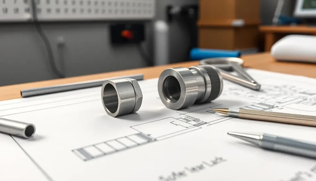
Right angle connector drawings define the physical configuration of electronic connectors where contacts meet the housing at 90 degrees. Engineers often make costly mistakes including incorrect dimensions, unclear orientation indicators, and missing clearance requirements.
These errors cause manufacturing confusion and assembly problems during production. Creating accurate Right angle connector drawing documentation with proper tolerances and complete reference information prevents expensive rework and ensures reliable signal performance in compact electronic designs.
Understanding Right Angle Connector Drawings
Right angle connector drawings show the physical configuration of electronic connectors where contacts intersect the main housing at 90 degrees. Engineers use these drawings during the design and manufacturing process to define the pin layout, housing dimensions, and positioning requirements.
Each right angle connector drawing includes information such as pitch (distance between contacts), stack height, and mounting style—essential references for circuit board compatibility.Manufacturers like Promax in China use these technical drawings to specify pogo pins, spring-loaded contacts, and magnetic connectors for consumer electronics, aerospace devices, and medical equipment.
Dimensional accuracy in these drawings directly impacts assembly reliability and signal integrity. Engineers analyze cross-sections, recommended PCB pads, and tolerances within these documents to minimize errors in mass production.
When key data points, like mating height or plating thickness, are stated clearly, downstream teams can fabricate and verify the connectors for consistent performance.Clear and well-annotated right angle connector drawings also help procurement teams compare specifications and ensure design intent matches delivered parts.
Promax’s engineering team aligns connector drawings with international certification standards, reducing miscommunications and rework during sourcing and assembly.
Common Mistakes To Avoid In Right Angle Connector Drawings
Errors in right angle connector drawings often cause assembly challenges or signal failures. Addressing the following mistakes helps engineers and sourcing professionals create clear, accurate connector documentation for Promax and other suppliers.
Incorrect Dimensions And Tolerances
Wrong or inconsistent dimensions on drawings create mismatched connections, leading to connector defects—especially in tight assemblies like medical probes or consumer electronics motherboards. Inaccurate tolerances also affect mating, housing, and pin fit, which impacts both mechanical alignment and electrical performance.
For example, a 0.05 mm error in pin pitch can prevent pogo pins from seating accurately in mating pads. Promax often advises customers to reference IPC-2221 standards for dimensioning and specify tolerances for both contact and housing features directly on drawings, minimizing the risk of miscommunication during manufacturing.
Failure To Indicate Proper Orientation
Omitting or unclear connector orientation in drawings frequently confuses manufacturing teams. Right angle connectors rely on specific alignment for both mechanical fit and signal integrity. For instance, a missing keying notch or polarization arrow can result in reversed board mounting, which makes pogo pin or spring-loaded connectors incompatible with the rest of the assembly.
Promax includes orientation indicators, such as pin 1 marks, in all connector technical sheets—ensuring end users understand exact connector positioning and alignment for PCB or cable integration.
Overlooking Clearance And Fit Issues
Missing clearance, mating, or mounting fit requirements in right angle connector drawings causes interference during both manual and automated assembly. Clearance details next to adjacent components or housings are critical in compact PCB layouts typical of aerospace and wearable device applications.
Examples include insufficient space for magnetic connectors near inductive coils or cable strain reliefs. Promax examines customer drawing packages for minimum insertion, extraction, and board edge clearances, specifying necessary standoff heights or insulation gaps to guarantee reliable fit in dense assemblies.
Incomplete Or Missing Reference Information
Drawings lacking complete reference data—such as material specifications, surface plating, part numbers, or revision histories—lead to errors during procurement, inspection, or quality audits. Omitted details often cause supply chain delays or part mismatches.
Including relevant standards (like RoHS compliance), finish codes for gold-plated contacts, and clear labeling of both male and female connector drawings in the documentation is standard practice. Promax always issues connector drawings with full revision markings, parts lists, and manufacturing notes, helping engineering and procurement teams compare specifications and source correct components for specialized applications.
Best Practices For Accurate Connector Drawings
Precision in right angle connector drawings improves manufacturing outcomes and reduces costly errors. Promax in China follows proven methods to align connector documentation with application and sourcing requirements.
Double-Checking Specifications
Reviewing connector specifications lowers the chance of dimensional mistakes in right angle connector drawings. Engineering teams at Promax confirm pin counts, pitch values, and housing dimensions for each pogo pin and spring-loaded connector product line before release.
Engineers check electrical ratings and tolerance stacks for each pin, using the final BOM (Bill of Materials) as a source of truth. Cross-verification with IPC-2221 guidelines verifies that design intent and standards compliance match, reducing risk in medical, aerospace, and consumer electronics projects.
Using Consistent Symbols And Notations
Standardizing drawing symbols and notations ensures that all connector details remain clear across engineering and procurement teams. Promax drawings use ISO-compliant graphic symbols, such as for pin one location, plating finishes, and mating orientation indicators, which help designers and contract manufacturers avoid assembly confusion.
Engineers at Promax use the same reference notations for part numbers and revision codes to streamline global supply communication. Consistent notation enables sourcing teams and customers to identify mating and magnetic solutions correctly, decreasing delays and errors in project timelines.
Conclusion
Getting right angle connector drawings right from the start pays off throughout the entire design and manufacturing process. Teams that prioritize accuracy and clear documentation avoid the setbacks that come with miscommunication and unexpected rework.
By leveraging industry standards and best practices, engineers and procurement teams can work together more efficiently and deliver reliable products. Staying vigilant about the details in connector drawings ensures smoother assembly, better signal performance, and fewer production headaches down the line.
Frequently Asked Questions
What is a right angle connector?
A right angle connector is an electronic component where the contacts meet the housing at a 90-degree angle. These connectors are use to change the direction of signal flow between circuit boards or devices, often saving space in compact designs.
Why is precision important in right angle connector drawings?
Precision is crucial because even small errors in dimensions, pin layout, or orientation can cause manufacturing issues, assembly problems, or signal failures. Accurate drawings help ensure reliable connections and reduce costly rework.
What are the most common mistakes in right angle connector drawings?
The most common mistakes include incorrect or missing dimensions, unclear orientation, incomplete reference information, and ignoring clearance or tolerance requirements. These mistakes can lead to mismatched parts and assembly errors.
How do technical drawings help in sourcing right angle connectors?
Technical drawings provide detailed specifications on pin layout, housing, and orientation. Procurement teams use these drawings to compare products and ensure that supplied connectors match the project’s exact requirements, reducing sourcing errors.
Why should engineers follow IPC-2221 standards for connector drawings?
IPC-2221 is an industry-standard that sets guidelines for electronics design, including connector drawings. Following this standard helps ensure quality, compatibility, and reduced risk of errors during manufacturing and assembly.
How can manufacturers prevent miscommunication when sourcing connectors?
Manufacturers can prevent miscommunication by providing clear, well-annotated drawings with consistent symbols and complete documentation. This ensures everyone—from engineers to procurement—understands the design intent and specifications.
What best practices improve the accuracy of right angle connector drawings?
Best practices include double-checking all dimensions, confirming pin counts, ensuring clear orientation indicators, using consistent symbols, and cross-referencing relevant standards like IPC-2221. Thorough documentation helps avoid errors and assembly issues.
What role does Promax play in ensuring connector accuracy?
Promax follows strict documentation procedures, uses ISO-compliant symbols, and aligns their drawings with IPC-2221 standards. This approach minimizes errors, improves communication between teams, and supports reliable manufacturing outcomes.


